Bolt Circle & Hole Pattern Coordinate Generator
Hole coordinates for bolt circles, rows and grids with DXF, SVG and G-code export · free, no signup
Coordinates
See Bolt Circle & Hole Pattern Coordinate Generator in action
Free Bolt Circle & Hole Pattern Coordinate Generator
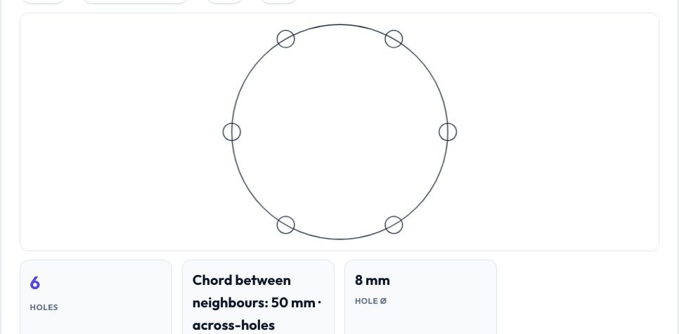
A bolt circle is a set of equally spaced holes on a circle — wheel hubs, flanges, pulleys, motor mounts. Enter the number of holes, the bolt-circle (pitch circle) diameter, a start angle and the centre, and the generator returns the exact X/Y coordinates and angle of every hole, the chord distance between neighbouring holes and the across-holes distance used for inspection. Presets fill common wheel patterns such as 5×114.3, 5×100, 4×100, 6×139.7 and the NEMA 17 4×31 mount.
Linear rows and rectangular grids (with rotation and optional centring) are covered too. A live preview draws the holes and the pitch circle; the coordinates can be copied as CSV, downloaded as a DXF or SVG with circles of your hole diameter, or exported as G-code with a G81 canned drilling cycle with your depth, feed and safe height — ready for a CNC mill or drill press with DRO.
Key features
Bolt circles with presets
Any count, PCD, start angle and centre; common wheel and flange patterns.
Rows and grids
Linear spacing, grid spacing and rotation.
Inspection data
Chord between holes and across-holes dimensions.
DXF, SVG, CSV, G-code
G81 drill cycle with depth, feed and safe Z.
How to use it
- Choose bolt circle, row or grid.
- Enter count, diameters or spacings.
- Check the preview and coordinates.
- Download DXF/SVG, copy CSV or export the drilling G-code.
Worked example
Example
6 holes on a 100 mm PCD starting at 0°: holes at (50, 0), (25, 43.301), (−25, 43.301), (−50, 0), (−25, −43.301), (25, −43.301); chord between holes 50 mm; across holes 100 mm.
Who uses this tool
Machinists and CNC users
Drilling coordinates and a ready G81 program.
CAD users
Check a bolt circle against calculated coordinates.
Makers
Design flanges and mounts accurately.
Tips for the best results
- Use the across-holes measurement to verify a drilled circle.
- For even hole counts measure opposite holes; for odd counts use the chord.
- Use a DXF import to place holes in CAD at exact positions.
- Check the G-code on your machine's dry-run before cutting.
Common mistakes to avoid
- Mixing up PCD and hole-circle radius.
- Forgetting the start angle on a flange with a keyed position.
- Running generated G-code without checking depth and safe Z.
Why use AZRS QuickFix?
It is 100% free, needs no signup and has no watermark or usage limits. The tool runs in your browser, so what you type stays on your device, and it works on phones, tablets and desktops. New tools are added every week — bookmark this page or browse the full QuickFix toolbox.
Frequently asked questions
What is PCD?
Pitch circle diameter: the diameter of the circle through the hole centres.
How is chord length calculated?
2 × R × sin(π / N) for N holes on a circle of radius R.
Is the G-code universal?
It uses standard G81 for Fanuc-like controllers (also GRBL variants with canned cycles).
Can I rotate a grid?
Yes — set the pattern rotation angle.