
Explore the Digital Filter Designer: Low-Pass & High-Pass
Design a real RC low-pass or high-pass filter, watch its Bode magnitude plot draw live, and see exactly how much a signal is attenuated at any frequency.
- Free to use
- No signup
- Nothing to install
- Runs in your browser
Illustration. Open the tool for the real thing.
See it in action
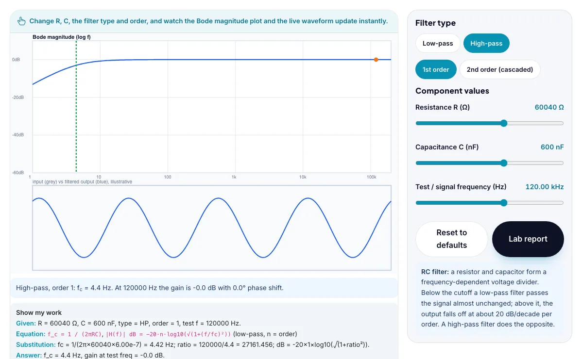
The Digital Filter Designer: Low-Pass & High-Pass with sample data entered and the result showing.
What is the Digital Filter Designer: Low-Pass & High-Pass?
Design a real RC low-pass or high-pass filter, watch its Bode magnitude plot draw live, and see exactly how much a signal is attenuated at any frequency. It runs in your browser, so a change to a setting or a drag on an object shows up at once.
Audio crossovers, anti-aliasing filters ahead of analog-to-digital converters, power-supply noise filters and sensor signal conditioning circuits all rely on exactly this RC low-pass/high-pass cutoff-and-roll-off design process.
3 steps to your result
Open the tool and follow along. Nothing to install.
What you get
An RC filter's cutoff frequency is fc = 1/(2 pi R C); above it a low-pass filter's output falls off, and below it a high-pass filter's output falls off.
Each filter 'order' (an extra RC stage cascaded on) doubles the roll-off steepness: about 20 dB/decade per order.
A Bode plot shows gain in decibels against frequency on a logarithmic axis, which turns the filter's smooth curve into a nearly straight-line roll-off far from the cutoff.
Pick R and C to hit exactly 1000 Hz cutoff.
Switch from low-pass to high-pass and see the curve mirror.
Add a second order and watch the roll-off steepen from 20 to 40 dB/decade.
Used for
Pick one to see how it fits.
Engineering learners
Engineering and technology students, makers, robotics clubs and teachers of design and technology.
Try it freeTeachers
For teachers: project the Digital Filter Designer: Low-Pass & High-Pass on the board, let students predict the result, then run it together and test this: Switch from low-pass to high-pass and see the curve mirror. For students: change one thing at a time and write down what changes.
Try it freeHow it compares
A plain look at this tool next to the usual alternative.
| This simulation | Textbook diagram | |
|---|---|---|
| Interactive | Drag, tap and change settings | Fixed picture |
| Install | Nothing to install | Not needed |
| Cost | Free to use | Depends on the book |
Questions people ask
Why does doubling the filter order double the dB roll-off per decade instead of the cutoff frequency?
Cascading a second identical RC stage multiplies the magnitude response of the first stage by itself, and since decibels are logarithmic, multiplying magnitudes adds their dB values - so the roll-off slope doubles from about 20 dB/decade to about 40 dB/decade, while the -3 dB cutoff point stays close to the same frequency.
Why is a log frequency axis used for a Bode plot instead of a normal linear axis?
A filter's response changes by a similar percentage over each doubling or decade of frequency rather than each fixed increment, so a logarithmic axis spreads that behavior out evenly and turns the far-from-cutoff roll-off into a straight line that is easy to read the slope from.
Is the Digital Filter Designer: Low-Pass & High-Pass free to use?
Yes. The Digital Filter Designer: Low-Pass & High-Pass is free, needs no signup or download and runs in your web browser. It is part of the Engineering group of AZRS simulations.
Does the Digital Filter Designer: Low-Pass & High-Pass work on a phone or tablet?
Yes. The Digital Filter Designer: Low-Pass & High-Pass takes touch input as well as mouse input, so you can use its 3 adjustable settings with a finger. A larger screen makes the controls and graphs easier to read.
How do I use the Digital Filter Designer: Low-Pass & High-Pass?
1. In the Digital Filter Designer: Low-Pass & High-Pass, use the controls to change Resistance R (Ω), Capacitance C (nF), Test / signal frequency (Hz). The simulation reacts instantly. 2. In the Digital Filter Designer: Low-Pass & High-Pass, pick an option such as Low-pass, High-pass, 1st order, 2nd order (cascaded) to switch modes or load an example. 3. Start with this experiment: Pick R and C to hit exactly 1000 Hz cutoff. Drag any glowing handle, object or slider with your mouse or finger and the Digital Filter Designer: Low-Pass & High-Pass responds in real time. 4. Change one setting at a time and watch which readout moves, then compare it with this idea: An RC filter's cutoff frequency is fc = 1/(2 pi R C); above it a low-pass filter's output falls off, and below it a high-pass filter's output falls off.
More free tools
Related to the Digital Filter Designer: Low-Pass & High-Pass.
Try the Digital Filter Designer: Low-Pass & High-Pass now
Design a real RC low-pass or high-pass filter, watch its Bode magnitude plot draw live. Free to use.
Try it free